

Traffic Light Controller Using Arduino build in 60sec Leave a comment
Traffic Light Controller Using Arduino project uses an Arduino board together with a minimal number of other components to create a basic three-way traffic light controller. It contains the traffic controller system’s code as well as a circuit schematic.
Table of Contents
The most widely used open-source microcontroller board for a variety of DIY and electronics projects is the Arduino. An Arduino-based traffic light controller is a basic electronic project. These days, personal vehicles are preferred by all. As a result, there are always more cars on the road, which causes traffic congestion.
A traffic light controller aids in maintaining appropriate traffic control and managing the flow of traffic. In order to prevent traffic jams and accidents, these devices are positioned at road crossroads or crossings. The systems use various light colors to indicate to the driver. As a result, avoiding traffic at the junctions is easy.
This project uses Arduino to control traffic lights. Through this electronic project, we will learn about traffic signals and their operation. This project is a basic traffic light demonstration system that we have set up for three sides or directions.
Need for Traffic Light Controller Using Arduino
Traffic conflicts and accidents can occur on roads when there is no oversight or advice. For traffic to flow in an orderly manner, traffic signals are necessary. A traffic signal is a tool used to direct drivers, telling them to follow the displayed sign.
Traffic lights lessen conflicts between vehicles arriving at intersection points from different directions by allowing everyone to cross the intersection point one at a time. In addition to promoting road safety, it facilitates straightforward traffic solutions.
Traffic lights come in various colors. Every light has a purpose and instructs drivers on what to do.
– Red light on: The vehicle needs to halt.
– When the yellow light appears, drivers must slow down and prepare to stop.
– With the green light on, a driver can either begin or continue driving.
Components Required
- Arduino Uno
- Breadboard
- LEDs (Red , Yellow , Green)
- Resistor(220 ohm)
- Dupont cables
Circuit Connection (LED with Arduino)
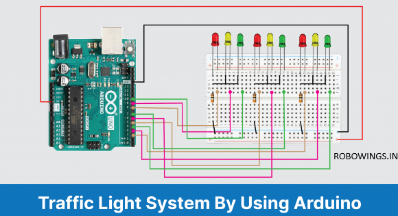
This is the circuit diagram for the Arduino-powered traffic light controller.
- Connect the Red, Yellow, and Green LEDs on the breadboard, in that order.
- Link the 220 Ohm resistor in series with the LED’s negative terminal.
- Join the ground with these negative terminals.
- Attach pins 2 through 10 to the positive terminals of the LEDs, in that order.
- Power the breadboard by using 5V and GND on the Arduino
The logic of This Traffic Light System Using Arduino Code
This traffic light controller has straightforward, understandable code. For a three-way road, we have traffic signals displayed. The LEDs will be shining in a precise order to produce an actual traffic light controller system.
One green LED will be ON and two red LEDs will glow simultaneously. Two yellow LEDs will also be turned on for a whole second. Every time the light turns from red to green, a yellow LED will glow. In short initially RED LED will light for 5 Seconds, then YELLOW for 1 second, and then Green LED will ON for 5 seconds.
The pins for the LEDs are defined as outputs from 2 to 10 in the code’s void setup. We have defined the routines to turn LEDs on and off in a certain order in the void loop section.
Code & Software
   void setup() {
  // configure the output pins
  pinMode(2,OUTPUT);
  pinMode(3,OUTPUT);
  pinMode(4,OUTPUT);
  pinMode(5,OUTPUT);
  pinMode(6,OUTPUT);
  pinMode(7,OUTPUT);
  pinMode(8,OUTPUT);
  pinMode(9,OUTPUT);
  pinMode(10,OUTPUT);
}

void loop()
{
  digitalWrite(2,1); //enables the 1st set of signals
  digitalWrite(7,1);
  digitalWrite(10,1);
  digitalWrite(4,0);
  digitalWrite(3,0);
  digitalWrite(6,0);
  digitalWrite(8,0);
  digitalWrite(9,0);
  digitalWrite(5,0);
  delay(5000);

  digitalWrite(3,1); //enables the yellow lights
  digitalWrite(6,1);
  digitalWrite(2,0);
  digitalWrite(7,0);
  delay(1000);

  digitalWrite(4,1); //enables the 2nd set of signals
  digitalWrite(5,1);
  digitalWrite(10,1);
  digitalWrite(2,0);
  digitalWrite(3,0);
  digitalWrite(6,0);
  digitalWrite(8,0);
  digitalWrite(9,0);
  digitalWrite(7,0);
  delay(5000);

  digitalWrite(9,1); //enables the yellow lights
  digitalWrite(6,1);
  digitalWrite(10,0);
  digitalWrite(5,0);
  digitalWrite(4,0);
  delay(1000);

  digitalWrite(8,1); //enables the 3rd set of signals
  digitalWrite(4,1);
  digitalWrite(7,1);
  digitalWrite(2,0);
  digitalWrite(3,0);
  digitalWrite(5,0);
  digitalWrite(6,0);
  digitalWrite(9,0);
  digitalWrite(10,0);
  delay(5000);

  digitalWrite(9,1); //enables the yellow lights
  digitalWrite(3,1);
  digitalWrite(7,0);
  digitalWrite(8,0);
  digitalWrite(4,0);
  delay(1000);
}
Advantages
- This system’s traffic light controller is practically implementable, and you have the ability to make it even more extensive.
- A crosswalk signaling system is included with this traffic light controller.
- By integrating external memory with the central controller, timings can be programmed during operation rather than being fixed during programming.
Limitations
- The project is only meant to serve as a demonstration of the system’s workings; it is not appropriate for real implementation.
- Pre-programming operations or manual operation are the two ways the project might be run. It is unable to manage both.
- The operator of real-time traffic controller systems possesses the authority to modify the timings and intensity of each lane’s traffic light.
Final Work
Thank you for being with me til the end of this project . i hope you have underdtood all the concepts about traffic light control and its importance. if you like this project, try to implement it and let me know your comments section’s experiences
